Managing Tolerances in Multi-Part SLA Architectural Models
Precision Strategies for Seamless Assembly, Accuracy & Presentation Quality
In architectural 3D printing, precision is everything. Whether you are producing a large-format site model, a detailed competition entry, or a plug model for planning review, tolerances determine whether parts assemble seamlessly—or require costly rework.
When working with multi-part SLA architectural models, tolerance management becomes even more critical. Unlike single-piece prints, multi-component models must account for resin shrinkage, support removal, finishing processes, and assembly alignment.
For architects and modelmakers using SLA (Stereolithography) 3D printing, understanding tolerances is not just a technical detail—it is essential to delivering accurate, professional presentation models.
This guide explains:
What tolerances mean in SLA modelmaking
How resin behaviour affects dimensional accuracy
Best practices for designing multi-part assemblies
Common tolerance mistakes (and how to avoid them)
Practical strategies for plug models and large-format builds
What Are Tolerances in SLA Architectural Models?
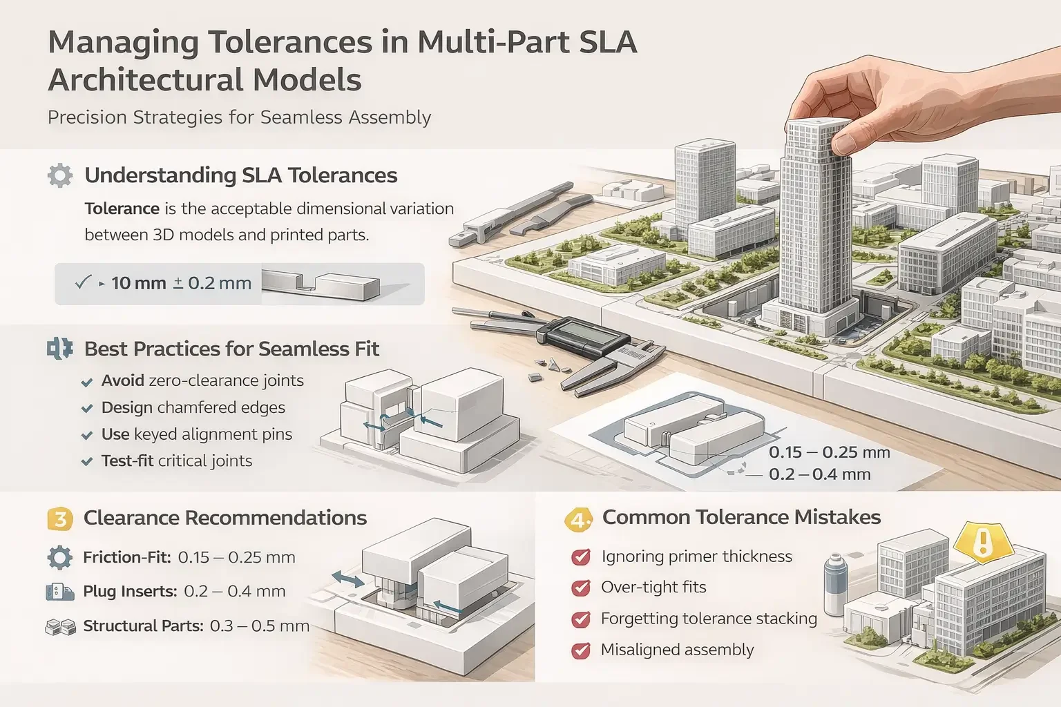
Tolerance refers to the acceptable variation in dimensions between the digital model and the physical print.
For architectural models, tolerances influence:
Interlocking components
Removable building inserts
Context plug systems
Multi-section site models
Snap-fit or friction-fit assemblies
In SLA 3D printing, tolerances are affected by:
Resin shrinkage during curing
Laser spot size and resolution
Layer thickness
Post-processing (washing, UV curing)
Sanding or priming
Even a 0.1–0.3 mm variation can impact assembly when dealing with fine architectural geometry.
Why Multi-Part Models Require Special Tolerance Planning
Large architectural models often exceed printer build volumes. This requires splitting into multiple components:
Site base sections
Building cores and façades
Landscape layers
Plug model inserts
Structural subassemblies
Without deliberate clearance planning, parts may:
Bind during assembly
Leave visible gaps
Sit unevenly
Warp slightly and misalign
Managing tolerances ensures components:
Fit predictably
Align accurately
Maintain structural stability
Preserve visual quality
Understanding SLA Dimensional Accuracy
SLA printing is known for high resolution and surface quality. However, dimensional accuracy is influenced by several variables.
Typical SLA Accuracy Range
Industrial SLA systems typically achieve:
±0.1 mm for small parts
±0.2–0.3 mm for larger components
But real-world architectural applications require accounting for:
Cumulative tolerance stacking
Part orientation
Resin type
Print thickness
For example, splitting a 600 mm site model into four sections can multiply dimensional deviation if tolerances are not planned carefully.
Resin Shrinkage & Post-Cure Behaviour
One of the most overlooked aspects of tolerance management is resin shrinkage.
During printing:
Resin polymerizes when exposed to UV light
Minor contraction occurs
During post-curing:
Additional shrinkage can happen
Internal stresses may relax
Thin elements may distort
For 3d architectural models featuring thin façade fins or delicate roof details, this can introduce micro-level distortion.
Best Practice
Avoid designing zero-clearance joints
Add intentional clearance allowances
Consider part orientation to reduce stress
Designing Clearance for Multi-Part Assembly
Clearance is the intentional gap between two mating components.
For SLA architectural models:
Friction-fit parts typically require 0.15–0.25 mm clearance
Insertable plug models often require 0.2–0.4 mm clearance
Larger structural joins may require 0.3–0.5 mm depending on scale
These values depend on:
Model scale (1:100 vs 1:500)
Surface finishing requirements
Whether parts will be painted
Example: Plug Model in Urban Context Base
When creating a removable building insert within a context model:
Model the cavity slightly oversized
Reduce insert footprint dimensionally
Add chamfered edges to ease placement
Account for primer thickness if painting
Without these adjustments, inserts may bind or require sanding.
Tolerance Stacking in Large Models
Tolerance stacking occurs when small dimensional variations accumulate across multiple parts.
For example:
0.2 mm deviation per section
Four adjoining sections
Result: 0.8 mm cumulative misalignment
In presentation models, this can create:
Visible seams
Misaligned roads
Step differences in terrain
How to Prevent It
Use shared reference geometry when splitting models
Avoid independent scaling of parts
Align parts using pinned or keyed systems
Use digital tolerance simulation before printing
Alignment Strategies for Multi-Part SLA Models
Successful assembly depends on intelligent joint design.
1. Keyed Alignment Systems
Use:
Dowel holes
Alignment pins
Rectangular tabs
Hidden internal ribs
These prevent rotational misalignment and reduce reliance on manual adjustment.
2. Chamfered Edges
Adding small chamfers to joining edges:
Reduces friction
Improves fit
Compensates for minor distortion
3. Stepped Interfaces
For plug models:
Use stepped rebates
Design internal ledges
Create controlled seating depth
This ensures inserts sit flush and stable.
Surface Finishing & Its Impact on Tolerances
Post-processing often alters dimensions.
Common finishing steps:
Support removal
Sanding
Priming
Spray painting
Each layer of primer can add approximately 0.05–0.1 mm thickness.
On tight-fitting assemblies, this matters.
Practical Recommendation
If parts will be painted:
Increase clearance slightly
Mask mating surfaces before spraying
Dry-fit before finishing
Ignoring finishing thickness is a frequent cause of assembly issues.
Scale Considerations
Tolerance strategy varies by model scale.
1:500 Context Models
Larger geometry
Less fine detail
Higher acceptable tolerance
1:100 Presentation Models
Fine façade articulation
Thin structural elements
Lower tolerance margin
At smaller scales, even 0.1 mm deviation can distort visual alignment.
Warping & Long-Span Components
Large flat prints are prone to slight warping during curing.
To minimize distortion:
Orient parts diagonally
Use internal structural ribbing
Avoid overly thin base plates
Print terrain in segmented sections
Large-format SLA models particularly benefit from structural reinforcement design.
Quality Control Workflow for Tolerance Management
A professional SLA workflow should include:
Pre-print design review
Clearance verification in CAD
Test print of critical joints
Dimensional inspection
Dry-fit assembly check
Controlled finishing process
Testing a small joint prototype before committing to a large-format build can prevent costly reprints.
Common Tolerance Mistakes in Architectural Modelmaking
Designing zero-clearance inserts
Ignoring primer thickness
Over-tight friction fits
Forgetting cumulative stacking
Splitting models without alignment references
Underestimating resin shrinkage
These errors can compromise both visual quality and delivery timelines.
Balancing Precision with Practicality
While SLA technology offers high accuracy, architectural models do not always require engineering-level tolerances.
The goal is:
Visual precision
Reliable assembly
Seamless presentation
Durable handling
Over-engineering tolerances can increase production time without improving outcome.
Effective tolerance management finds the balance between:
Digital perfection
Physical realism
Practical assembly
Final Thoughts: Precision as a Competitive Advantage
In multi-part SLA architectural models, tolerance management separates average outputs from exceptional ones.
When tolerances are planned correctly:
Plug models fit effortlessly
Sections align seamlessly
Finishes remain crisp
Assembly time decreases
Client presentations feel refined
For architects working at competition or planning stages, these details reinforce professionalism and design credibility.
Precision is not just about accuracy—it’s about confidence.
And in architectural modelmaking, confidence is built on control.